Table of Contents
Objectives
- Study of different excitation schemes and their comparison
- The excitation schemes comparison based on settling time and deviation from the steady value of different parameters.
Introduction
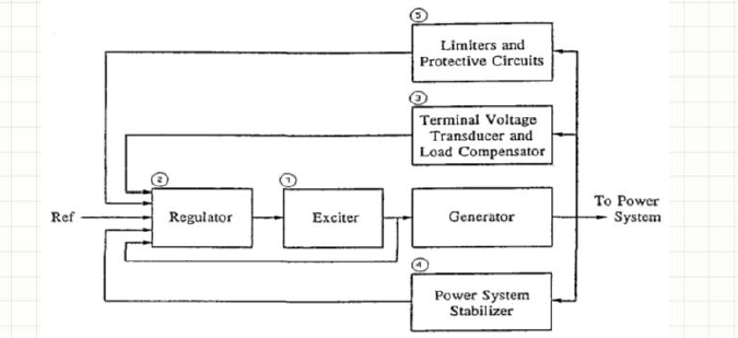
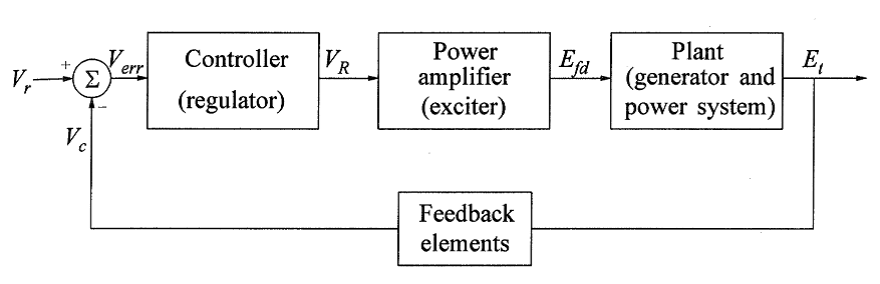
Excitation and Voltage Regulation
Every power generation system requires some means of controlling the voltage and/or current produced by the machine. The output of a generator is normally controlled by controlling the current in the field of the generator, the speed being constant for a set frequency. Various excitation systems are possible and all usually include some system of sensing and controlling the generator output voltage.
The simulation in this tutorial is done using Matlab/Simulink environment. For an introduction to Matlab/Simulink for Power Engineers, you may visit the post.
Matlab is a proprietary software by Mathworks Inc. The latest MATLAB and Simulink Student Suite R2018a![]() can be purchased at a good price from Amazon.
can be purchased at a good price from Amazon.
For a detailed study of excitation systems, their working and type, have a look from famous book Power System Stability and Control![]() by P. Kundur.
by P. Kundur.
You can buy to book from Amazon at an amazing deal:
Types of Excitation Systems
Excitation systems vary from the very simplest to rather complex systems. The simplest would consist of a battery to supply excitation power to the generator field along with a rheostat to control the amount of excitation current, that being managed manually by an operator. This system is generally not acceptable; therefore, some means of automatic control is desired.
Most modern excitation systems involve electronics in the voltage sensing and regulation and are relatively fast and accurate. Many exciter systems consist of an excitation generator driven by the engine either directly or by a system of pulleys and belts. The excitation generator puts out the power, and a voltage regulator controls that generator’s field in such a way that the main generator’s field is under control.
Classified into three broad categories based on the excitation power source:
- DC excitation systems
- AC excitation systems
- Static excitation systems
DC Excitation Systems
- utilize dc generators as the source of power; driven by a motor or the shaft of the main generator; self or separately excited
- represent early systems (1920s to 1960s); lost favour in the mid-1960s because of large size; superseded by ac exciters
- voltage regulators range from the early non-continuous rheostatic type to the later system using magnetic rotating amplifiers
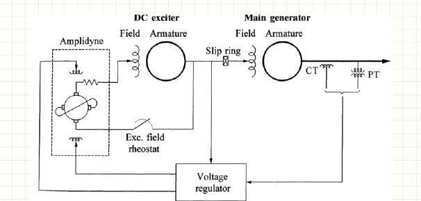
The figure shows a simplified schematic of a typical dc excitation system with an amplidyne voltage regulator
- self-excited dc exciter supplies current to the main generator field through slip rings
- exciter field controlled by an amplidyne which provides incremental changes to the field in a buck-boost scheme
- the exciter output provides rest of its own field by self-excitation
AC Excitation Systems
- use ac machines (alternators) as the source of power
- usually, the exciter is on the same shaft as the turbine-generator
- the ac output of exciter is rectified by either controlled or non-controlled rectifiers
- rectifiers may be stationary or rotating
- early systems used a combination of magnetic and rotating amplifiers as regulators; most new systems use electronic amplifier regulators
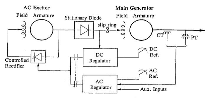
Stationary rectifier systems
- dc output to the main generator field supplied through slip rings
- when non-controlled rectifiers are used, the regulator controls the field of the ac exciter; Fig. shows such a system which is representative of GE-ALTERREX system

 Non-Controlled Stationary rectifier systems
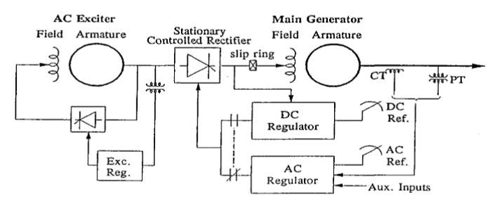
When controlled rectifiers are used, the regulator directly controls the dc output voltage of the exciter; Fig. shows such a system which is representative of GE-ALTHYREX system
Rotating rectifier systems
- the need for slip rings and brushes is eliminated; such systems are called brushless excitation systems
- they were developed to avoid problems with the use of brushes perceived to exist when supplying the high field currents of large generators
- they do not allow direct measurement of generator field current or voltage
 Static Excitation Systems
- all components are static or stationary
- supply dc directly to the field of the main generator through slip rings
- the power supply to the rectifiers is from the main generator or the station auxiliary bus
Setup
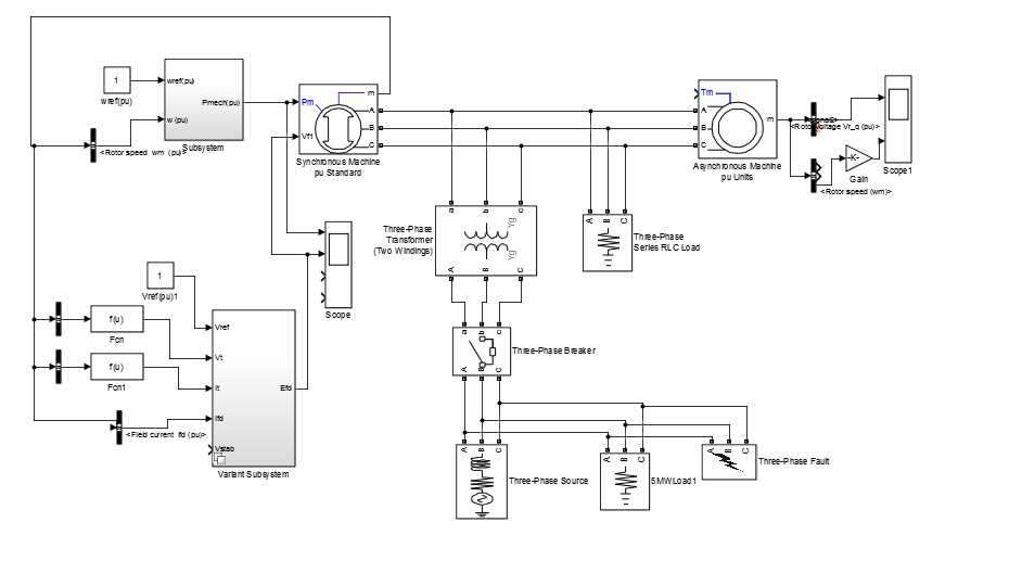
Procedure
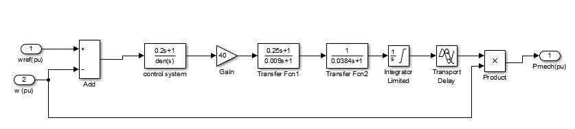
Diesel Engine Governor Block:
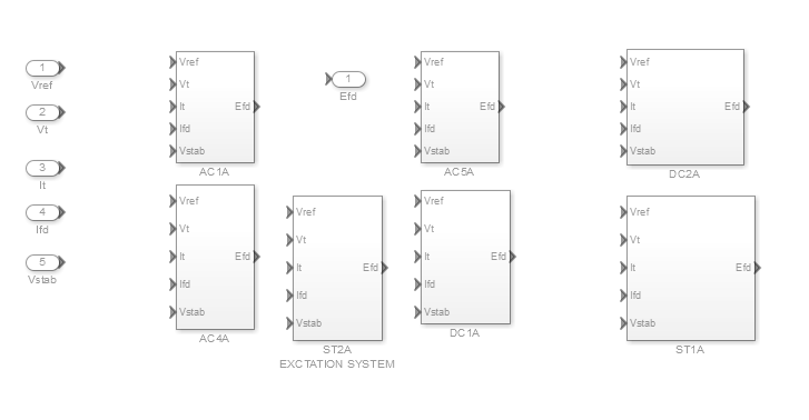
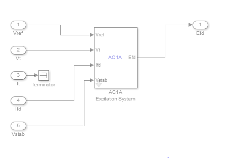
Excitation Block:
Task 1
Understand the complete load flow and determine at which time which source is feeding the power to the circuit.
Task 2
Right-click on the Excitation block, go to variant option and then to override using the option to select all the excitation models one by one. Observe the parameters discussed in the introduction for each of the Excitation blocks and make comments on all the waveforms obtained.
Task 3
Based on the waveforms taken in above step, decide which one are which group of excitation systems are better than the others.
Conclusion
- Due to change in excitation scheme, there is a change in settling time and deviation from the steady value of different parameters


Aqib Ali says
bhai ap ki website mjy bht achi lgi , m bsse ks student hu , electrical engineering ko nh smjhta mgr outlook sy lg rha hy k content bhi bht acha hoga is site pr , ap ka confidence esa hy k koi appreciate kye bgair nh reh skta , baqi websites ko kaamyaab hone m bht mehnat or tyme lgta hy , ap lgy rho inshAllah sb set hojae ga , pr apka jo website bnane ka talent hy ise mzeed use kro or or cheezo’n ko ly kr website bnao , electrical engineering parhne waly dunya m km hn , mgr khana khane waly sb hn , kapra pehanne waly sb hn , koi general topics uthao us pr blogging kro , ese ese titles do jo zada tr log search krty hon or dosri sites pr na hn phir google ko khud hi apki site uper search engine m laani pry gi , apni detail site pr jane k liye m ny kbhi khi cmnt nh kiya pr aj krna pra <3
Muhammad Sarwar says
Hey Aqib!
Thanks for your kind appreciation and suggestions.
Regards,